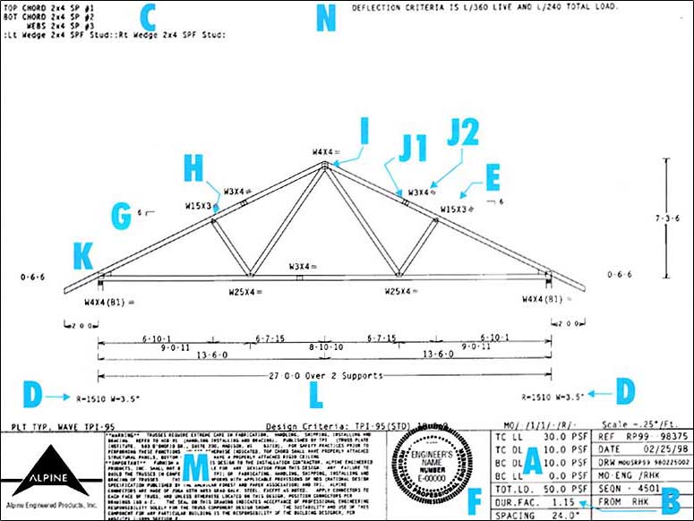
A - Design Loading
Top and bottom chord dead and live loads (including snow load) in pounds per square foot as used in the analysis.
B - Load Duration Factor
An adjustment of allowable design values of lumber and fasteners for load durations other than normal.
C - Lumber Specifications
Lumber size, species and grade for each member as used in the analysis.
D - Reaction
The force in pounds on the bearings produced by the truss at design load, and the bearing width.
E - Connector Plates
The gage, series, size and orientation.
F - Engineers Seal
Seal of the registered professional supervising the design.
G - Slope
The vertical rise in inches for every 12 inches of horizontal run.
H - Panel Points
The joints of the truss where the webs intersect the chords.
I - Peak
The intersection of two chords where the slope changes from positive to negative. Generally at the centerline of the truss.
J1 & J2 - Splices
Where two chord pieces join together to form a single member. J1 shows the location, J2 the corresponding connector plate.
K - Heel
The point of the truss where the top and bottom chord intersect, generally at the bearing point.
L - Span
The nominal span based on out-to-out dimensions of the supports or the bottom chord length, whichever is greater.
M - General Notes
Notes that apply to all Alpine design drawings.
N - Special Notes
Notes that apply only to this specific design drawing.